All text and photographs © 2002-2011 Andre Knecht / ARK digital. All rights reserved.
(I welcome, and feel flattered by, anybody posting links to this (or any other) page on my website. However, I do not welcome, nor do I allow, un-credited and un-attributed direct, or “blind,”links to any of the material therein. It’s simply not cool. Thank you.)
Please Note: I am, at best, an amateur when it comes to photography and/or creating web sites. This page is a loving tribute to what has to be one of the all-time great analog synthesizers. I no longer own it, but I revel in the knowledge that it found a good new home, that it is in very good hands indeed, and that its voice will be heard worldwide.
Roland System 700 Modular Synthesizer
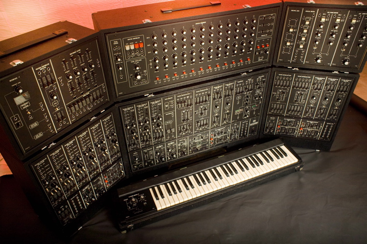
System 700 (fig. GS-01) - Brawn and beauty.
OVERVIEW
With the benefit of a “late” start (1976), Roland created a powerful masterpiec by “adopting” some of the best design features seen heretofore, by improving a number of others, and by introducing a few innovations of its own. Wide-range and ultra-stable VCOs, VC delays & phasers, versatile filters and a great sequencer, made the 700 a “synth for the ages.” It still is.
Rather than to describe a system 700 in detail, here are a couple of links to sites that already do a good job at that.
Synth Museum.com - System 700
Sonic State.com - Roland System 700
The system for sale is in its classic, and most desireable, seven-cabinet* configuration:
(* “Blocks,” in “Roland-speak”)
Block 1 - Main Cabinet (lower center)
Block 2 - Keyboard
Block 3 - Sequencer (upper center)
Block 4 - VCO Bank (lower left)
Block 5 - VCF & VCA Bank (lower right)
Block 6 - Interface / MultiMode Filter (upper left)
Block 7 - Effects / Switch (upper right)
Block 1 - Main Console
Main Console (fig. 1-01) - Complete View
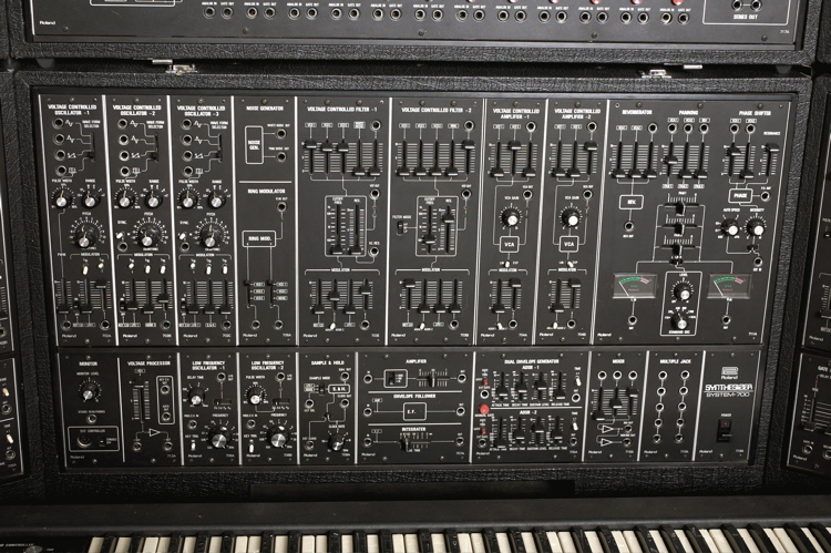
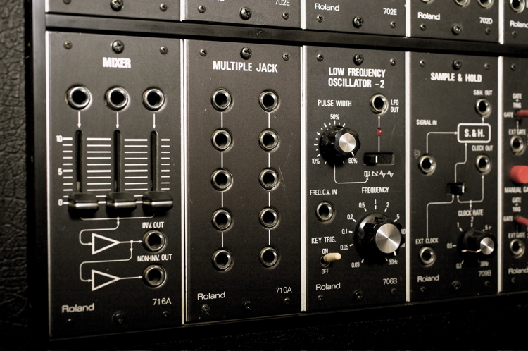
The 700’s Main Console is an extremely powerful synth... all by itself. Think of it as an ARP 2600 on steroids and you’ll be scratching the right surface. Its power and versatility stem from 3 VCOs, 2 VCFs, 2 VCAs, 2 ADSRs, 2 LFOs, Noise Generator, Ring Modulator, Sample & Hold, Reverb, Phaser, 8 (!) audio mixers (1 stereo), 7 (!) CV Mixers, 2 Multiple Jack Panels, Voltage Amplifier, Voltage Processor/Inverter, Envelope Follower, Integrator, Tuning/Test Reference Oscillator, Monitor Section (headphones), etc.
Borrowing a page from the ARP school of synth design, commonly used paths (audio signals and control voltages) are pre-wired and then normalled (and/or half-normalled) to various modules in the cabinet - eliminating a lot of otherwise repetitive and cumbersome patching.
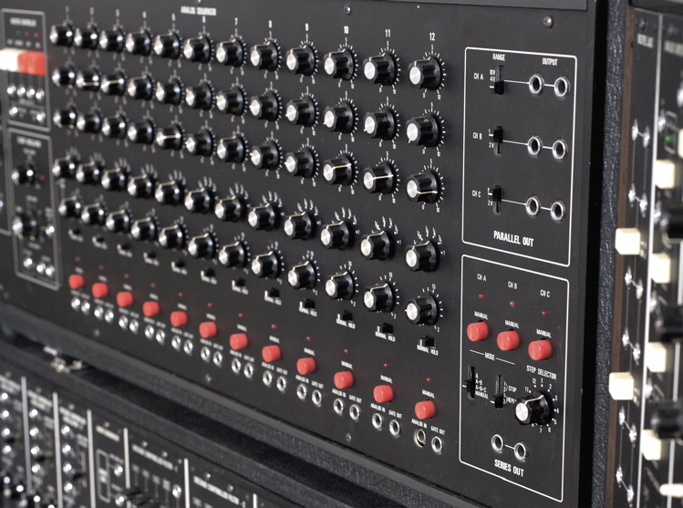
Main Console (fig. 1-02) - Left-Section Overview
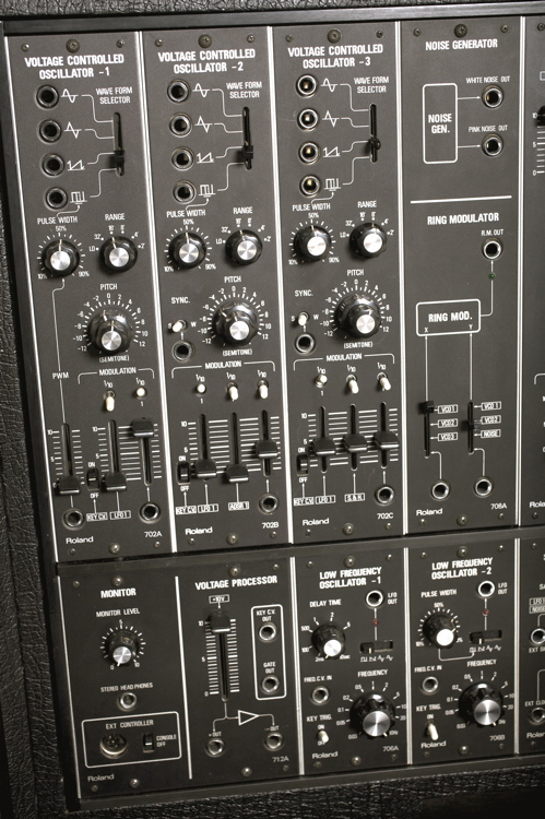
On the VCOs, note the dual concentric “coarse” and “fine” pitch adjustment knobs, in addition
to the Moog-style octave-stepped “Range” switch. Like on a Moog, setting the latter to “LO”
turns the VCO into a LFO. Each VCO has a set of normalled VC modulation inputs which can be
mixed. Note the “1/10” toggle switch above each modulation attenuator, allowing for extremely
fine adjustments.
Main Console (fig. 1-03) - VCO Detail
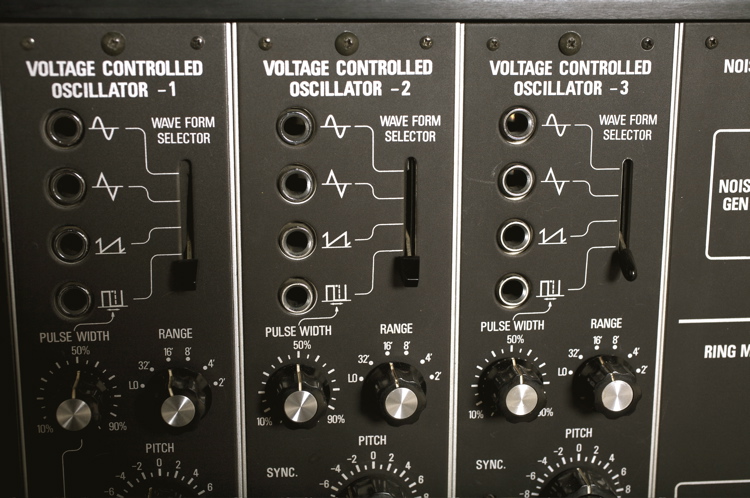 The four basic analog waveforms are always available simultaneously via their indivual outputs. The Waveform Selector determines which of the four appears at the Input Mixers of the VCF, Ring Modulator, and VCA modules.
Main Console (fig. 1-04) - Mid-Section View
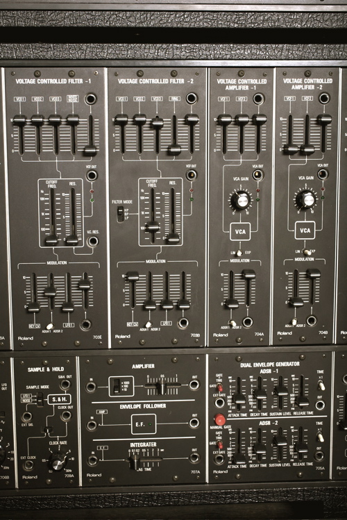
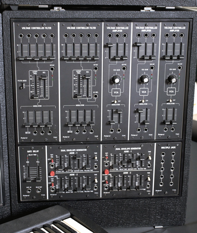
An illustration of good design: Each of the VCFs (top-left) features an audio input mixer with
four normalled ins + a patchable 5th one. Cutoff Freq modulation inputs feature a 3+1 CV Mixer.
Note the white toggle switches selecting ADSR 1 or 2 at the normalled inputs. The whole
concept is found again on the adjacent VCAs (on the right), albeit with two fewer ins of each.
VCF-1 (703E) is a classic 24dB/octvae fixed low-pass design.
VCF-2 (703B) is a variable-mode filter (High-Pass, Band-Pass, Low-Pass).
Main Console (fig. 1-05) - Right-Section View
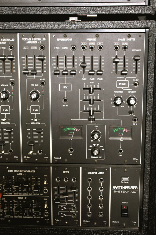
The system’s 711A (top-right) puts to shame most analog synths’ output sections (when and
if they have one). Spring reverb (+3ch input mixer), V-controlled Phaser (+2ch input mixer
& LFO), and a Test-tone/tuning oscillator, all feed a 3x2 Audio Mixer with pan sliders.
The twin output busses feature back-lit VU meters.
Block 2 - Keyboard Controller
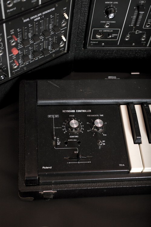
Keyboard (fig. 2-01) - Control Panel Detail
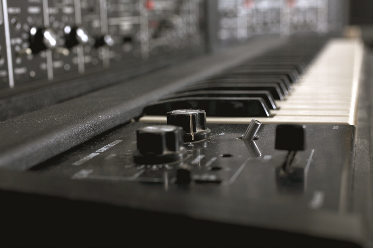
Keyboard (fig. 2-02) - Obligatory “artsy” shot
The keyboard, like all early Roland Keyboards, is (quite frankly) crap. If you ever had the pleasure of playing a SH-1000, SH-2000, System 100 (not 100m), you know that to be true. Use a MIDI-to-CV converter (with or without a keyboard) and put this one in a closet. Enough said.
Block 3 - Sequencer
Sequencer (fig. 3-01) - Complete View
Like many of the 700’s modules, the sequencer is a sophisticated, versatile and powerful implementation of the concept. Innovative and some unique (to this day) features, make the 717A one of the most desireable components of the system and a milestone in the field.
Sequencer (fig. 3-02) - Controller & Clock Detail
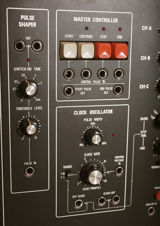
The Pulse Shaper is used to “condition” external and/or recorded sequencer pulse signals to be used
as transport commands (i.e. Start, Continue, Stop, End), or to trigger other synth functions.
Sequencer (fig. 3-03) - Step, Output & Running Mode Detail
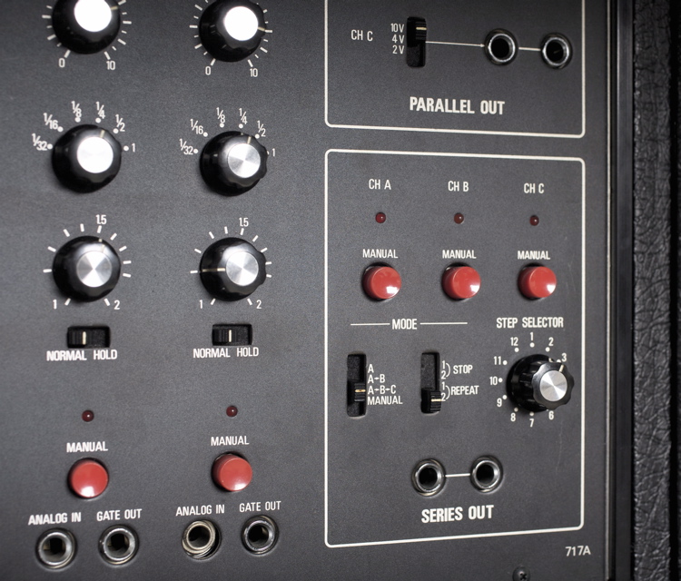
The duration (timing) for each of the 12 steps on the 717A can be adjusted by 1) a switch offering musical values (whole note to 1/32) and
by 2) a multiplier for the selected value. The latter enables the creation of rhythmic patterns with dotted notes and tuplets. Any step can be
put in “Hold” mode, muting its gate at the clock, and retaining the previous step’s CV, thus allowing the programming of rests.
Unique to the 700’ sequencer, is the inclusion of an “Analog In” for each step, which accepts both audio and CV signals. This turns the
717A into a programmable electronic switch. When a signal is present at the Analog In, the individual step pots on rows ABC will act as attenuators for each input. Slick!
Block 4 - VCO Bank
VCO Bank (fig. 4-01) - Complete View
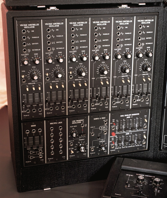
The top row of Block 4 adds six VCOs, for a total nine! These are joined on the bottom row by a Mixer, a 2 x 5 Jack-Mult,
a third dedicated LFO, a second Sample & Hold and ADSRs 3/4.
Unlike the VCOs found on the Main Block, these omit the Waveform Selector (because their outputs aren’t normalled
anywhere), but they gain patchable ins for their modulation sources. A defeatable KBD CV is normalled to all VCOs.
VCO Bank (fig. 4-02) - Additional Modules’ Detail
Gate signals are normalled to the LFO and the pair of ADSRs.
Block 5 - VCF & VCA Bank
VCF & VCA Bank (fig. 5-01) - Complete View
The top row adds a second instance of both the 12dB/oct MultiMode and the 4-pole 24dB/oct LowPass VCFs.
Three VCAs, a Gate Delay, four ADSRs (for a total of 8!) and a third 5x2 Jack-Mult panel round out Block 5’s facilities.
As was the case in Block 4, the absence of normalled signals (with the exception of the BKD CV and Gates), each module’s
Audio and CV input mixers become fully patchable.
VCF & VCA Bank (fig. 5-02) - Gate Delay & Dual ADSR Detail View
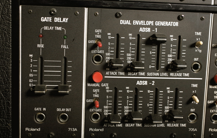
Delaying Gate signals is a time-honored technique on modular systems. Discrete delay times for the Rise (Attack) and Fall (Release) portions
of a Gate further expands the usefulness of the process. As in Block 4, Gate signals are normalled here to the pair of Dual ADSRs.
Block 6 - Interface & MultiMode Filter
Interface & MultiMode Filter (fig. 6-01) - Complete View
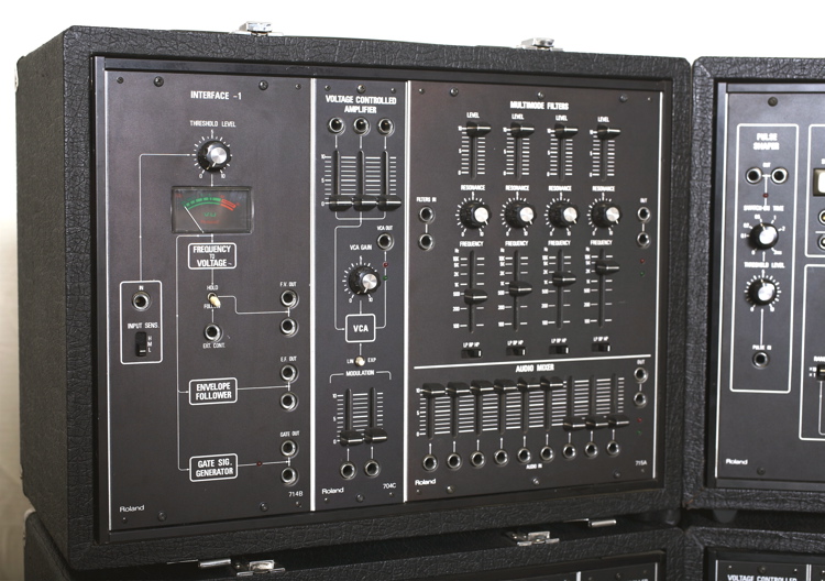
In Block 6, The Interface (Frequency-to-Voltage converter + Envelope Follower + Schmidt Trigger) is augmented by a sixth VCA, a versatile MultiMode Filter, and a 9-input Audio Mixer. (Nine VCOs, nine Mixer Inputs. Coincidence?)
Block 7 - Effects & Switch
Effects & Switch (fig. 7-01) - Complete View
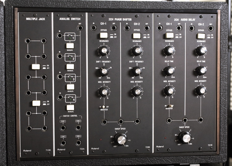
Block 7 (L to R)
Variable Jack Mult panel, offering the following configurations: a) three 1x3; b) one 1x3 + one 1x7; c) 1x11.
Four-way Electronic Switch;
Two-Channel Phase Shifter;
Two-channel Audio Delay.
System 700 (fig. GS-02) - “Night” view
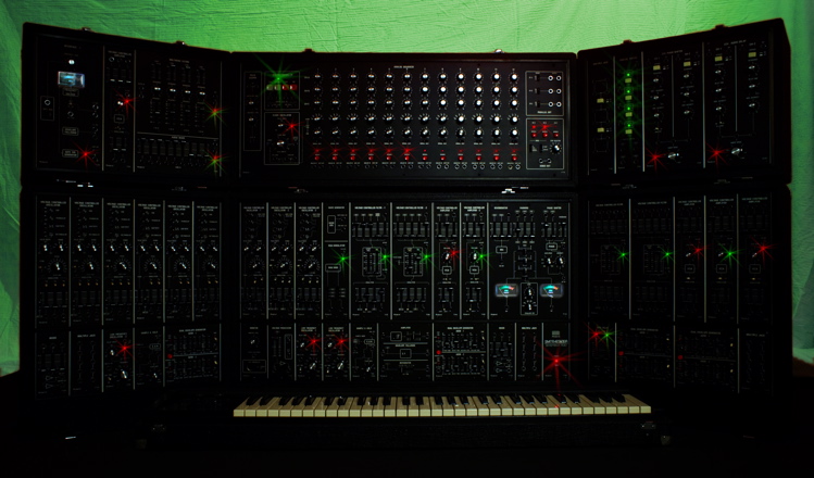
An attempt at creating a bit of “Gear Porn.” The 700’s LEDs are small and recessed into the modules’ front panel surface, making them not
nearly as bright as those found on a Moog, for example. They are perfectly visible and functional to the naked eye — just not as easily
captured with a camera. Here, their presence has been “enhanced.”
About The Pictures
1) Some pictures (the better ones) were taken with the help and photographic equipment of my friend Warren Eig.
2) I took a few additional shots with my Cheezotronic 9000-X camera (and abilities to match).
3) A handful of the pictures (like the one seen at the top of this page, for example) have been, as the Brits would say, “tarted up“ a bit with Photoshop™. (For those, I was again aided and abetted by the capable and patient Warren Eig). This was done as a deliberate attempt to appeal to (and exploit) the “Gear Slut” lurking inside all of us. For that, I make no apologies.
Besides, I’m up-front about it and I am identifying these with a “GS-” prefix. (As seen above.)
4) None of the pictures have been doctored to conceal any cosmetic flaws.
Last but not least…
All text and photographs © 2002-2011 Andre Knecht / ARK digital. All rights reserved.
(I welcome, and feel flattered by, anybody posting links to this (or any other) page on my website. However, I do not welcome, nor do I allow, un-credited and un-attributed direct, or “blind,”links to any of the material therein. It’s simply not cool. Thank you.)